
This post follows the Getting Started with nRF24L01+ on Arduino. If the resulting board from that is a little too rough around the edges, it can be built instead on a proper prototype shield for a few more dollars.
Stuff we need
New Parts
The changes from the original Getting Started board are that you need these parts instead of the corresponding parts from that post.
Same Parts
You still need these…
- 2.4G Wireless nRF24L01+ Module $4.00
- 2.54mm 2x4Pin Female Header (5Pcs) $1.50
- Solder cable – 7cm (10pcs) $0.50 (Or get some wire at Home Depot and cut it yourself)
Building it
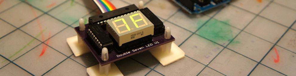
Follow the instructions in the Getting Started with nRF24L01+ on Arduino. The protoshield doesn’t have labels on the grid, so you can use the photos for reference.
Using it
The stackable headers are handy because you can stack another sheild atop it. However, the radio is a little too high for that. You have a couple options:
- Skip the 2×4 header and solder the module directly to the shield.
- Add a second set of stackable headers, so the shield atop this one is up a bit higher still.

First.. Thanks for this great library! I love it and have been using it for a number of projects. One example of code I would like to ask you to post is the ability to exchange information between two devices when they don’t know what each others roles are. In other words, you would need to switch roles back and forth for each device until they connect (one in receive mode and other in send mode) then they can exchange information like each others ID or GPS location. I kind of have it working but I’m sure you can support it in a much more eloquent way.
Thanks! Yeah, I can see the value of doing that definitely. Thanks for the suggestion, I’ll definitely keep it in mind as a future improvement.
Hello Maniabug, Thank you for posting great information about the nRF24 Module. I have recently purchased the Sparkfun WRL-00152 Transceiver nRF2401A. Unfortunately this Pin assignment is different as the one which you used (1 GND,2 VCC,3 CE,4 CSN,5SCK,6 MOSI,7 MISO,8 IRQ).
my pin# Arduino Assignment:
2 Nrf2401 transceiver pin DR1
3 Nrf2401 transceiver pin CE
4 Nrf2401 transceiver pin CS
5 Nrf2401 transceiver pin CLK
6 Nrf2401 transceiver pin DAT
Could you please give me an hint how I could use this module with your library ?
This module uses the nRF2401A, not the nRF24L01+ that is described in this post. The two may be compatible, but I have never tried them so I have no advice to offer on the topic, sorry.
Hi Guys,
library tested and works fine, tks for this.
But now i have a problem to solve. Each tx ( only 4) after power-up must ask authorization for inclusion in the network (maybe prob 0 ) from receiver and wait for a new address , so start working in the network. Have you any suggestion for this procedure?
Tks a lot
Renato
Sorry, I can’t make out the problem from this description. Perhaps you could provide more detail on what you’re trying to do, what you tried, and what results precisely you got?
Actually I think I know what Renato was getting at here. Setting up the remote nodes back to the receiver in a configuration where they do a request to the receiver -> receive a new address (or token perhaps of some kind) that they’re now permitted to send to the receiver, in effect “pairing” transmitters to the receiver more “dynamically” rather than having to hard code node ID’s and network addresses.
I can think of any number of scenarios where a configuration like this would be extremely helpful (alarm devices or remote key fobs perhaps) where you could more readily add/remove permitted devices from the network.